A PCB (Printed Circuit Board) is a rigid board used in electronics. FPC (Flexible Printed Circuit), also known as a flexible circuit board or flex board, is a flexible circuit board. It is commonly referred to as a flexible board. Miniaturization of electronic products is an inevitable trend in development. For many consumer products, surface mount components (SMD) are assembled on FPC due to space constraints, facilitating the overall assembly of the device. FPC has found widespread application in digital products such as calculators, smartphones, digital cameras, and camcorders. Conducting SMD surface mount assembly on FPC has become one of the trends in SMT.
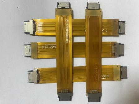 Pic. 1-1 FPC samples Pic.
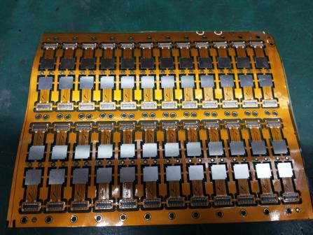 1-2 FPC samples with steel stiffeners
The SMT (Surface Mount Technology) process requirements for FPC (Flexible Printed Circuit) differ significantly from traditional rigid PCB (Printed Circuit Board) SMT solutions. To achieve success in the FPC SMT process, proper positioning is of utmost importance. Due to the inherent flexibility and softness of FPC boards, it's essential to use dedicated carriers or fixtures. Without them, it's impossible to secure and transport the FPC boards, which are fundamental for processes like printing, component placement, and reflow soldering in SMT. The following are detailed descriptions of key process steps in FPC SMT production, including pre-treatment, fixation, printing, component placement, reflow soldering, testing, inspection, and separation:
1.FPC Pre-treatment
Due to the soft characteristics of the FPC board, the factory is generally not vacuum packaging,easy to absorb moisture in the air during transport and storage.Thus need to do pre-baking treatment before SMT, the moisture will be slowly forced out. Otherwise, under the impact of the high temperature of reflow soldering, FPC absorbed moisture quickly vaporised into water vapour protruding from the FPC, easily resulting in FPC delamination, blistering and other defects.
Pre-baking conditions are generally 80-100 ℃ time 4-8 hours, under special circumstances, the temperature can be raised to 125 ℃ or more, but need to shorten the baking time accordingly. Before baking, be sure to make a small sample test to determine whether the FPC can withstand the set baking temperature, you can also consult with the FPC manufacturer for appropriate baking conditions. FPC stack should not be too much when baking, 10-20PNL is more appropriate, some FPC manufacturers will put a piece of paper between each PNL isolation, need to confirm that the isolation of the paper can withstand the set baking temperature, if not need to remove the isolation of the paper, and then baked. After baking, the FPC should have no obvious defects such as discolouration, deformation, warping, etc., and should be passed by IPQC before being put into the lines.
2.Production of Special Carrier Plates
According to the production files, read the hole positioning data of the FPC to manufacture high-precision FPC positioning fixture and special carrier plates, so that the diameters of the positioning pins on the positioning fixture match the diameters of the positioning holes on the carrier plates and the positioning holes on the FPCs. Many FPCs are not of the same thickness because of the need to protect part of the line or for design reasons, some are thicker while others are thinner, and some have stiffeners, so the combination of the carrier plate and the FPC needs to be processed according to the actual situation of grinding and grooving to ensure that the FPCs are flat during printing and mounting. The material of the carrier plate should be light and thin, high strength, low heat absorption, fast heat dissipation, and small warping and deformation after many thermal shocks. Commonly used carrier plate materials include synthetic stone, aluminium plate, silicone plate, special high-temperature-resistant magnetised steel plate, and so on.
Ordinary carrier plates:
Ordinary carrier plate is easy to design, fast proofing. Commonly used ordinary carrier plate material is engineering plastics (synthetic stone), aluminium plate, etc., Engineering plastics carrier plate life is about 3000-7000 times, easy to operate, better stability, not easy to absorb heat, not hot, the price is more then 5 times compared with aluminium plate . Aluminium carrier plate absorbs and dissipates heat quickly, there is no temperature difference between inside and outside, deformation can be simply repaired, cheap, long life, the main disadvantage is too hot, have to use insulated gloves to take.
Silicone carrier plates:
The material is self-adhesive, FPC directly stick to it, without tape, and easier to remove, no residual adhesive, and high temperature resistance. Silicone carrier plates in the use of the process will be aging viscosity decline, the use of uncleaned viscosity during the period will also decline, the life of a shorter, up to 1000-2000 times, the price is also higher.
Magnetic Carrier plates:
special high temperature (350 ℃) steel plate to strengthen the magnetisation performance processing, to ensure that the reflow soldering process ‘permanent magnetism’, good elasticity, good flatness, high temperature without deformation. Because of the enhanced magnetisation properties of the steel sheet has been the FPC surface compression and flattening, FPC in the reflow soldering to avoid being blown up by the reflow soldering wind weld defects, to ensure that the welding quality is stable, improve the yield rate. As long as it is not man-made damage or accidental damage, it can be used permanently and has a long life. Magnetic fixtures also provide thermal protection for FPC, and will not cause any damage to FPC when removing the board. However, magnetic fixtures are complicated in design and high in unit price, and only have cost advantages in mass production.
3.Production process.
We are here to take the ordinary carrier board as an example to detail the SMT points of FPC, the use of silicone or magnetic fixtures, FPC fixed to be much more convenient, do not need to use the tape, the following printing, placement, welding and other processes are the same process points.
FPC fixing→ solder paste printing→ SPI → components placement→ Visual check → Reflow→ FA inspection→ QC inspection
FPC fixing:
Before SMT, have to keep FPC on the carrier plates.Reminder:During fixing on the carrier plates to process of printing,placements and soldering, the storage time more shorter, more better.
There are two types of carrier plates with and without positioning pins. Carrier plates without locating pins are used in conjunction with locating templates with locating pins.
First, the carrier plate is placed over the locating pins of the template so that the locating pins are exposed through the locating holes on the carrier plate, the FPCs are placed one by one over the exposed locating pins, and then secured with adhesive tapes, and then the carrier plate and the FPC locating templates are separated for printing, mounting, and soldering.
The carrier board with locating pins already has several spring locating pins about 1.5 mm long, so that the FPCs can be placed one by one directly on the spring locating pins of the carrier board and then secured with adhesive tape. During the printing process, the spring-loaded pins can be pressed into the carrier plate by the stencil without affecting the printing result.
Method 1 (single-sided tape fixing): Use thin high-temperature resistant single-sided tape to fix the four sides of the FPC on the carrier board, so as not to allow the FPC to have offset and warping, the viscosity of the tape should be moderate, easy to peel off after reflow soldering, and there is no residual adhesive on the FPC.
Method 2 (double-sided tape fixed): first use high-temperature double-sided tape on the carrier board, the effect is the same as the silicone board, and then paste the FPC to the carrier board, pay special attention to the viscosity of the tape can not be too high, or reflow soldering after the peeling, it is easy to cause the FPC torn. The viscosity of double-sided adhesive tape will gradually become lower after repeated passes through the furnace, and must be replaced immediately when the viscosity is so low that the FPC cannot be fixed reliably.
Solder paste printing
Because the carrier plate is loaded with FPC by tape, that its plane is not consistent, so the printing surface of the FPC can not be like the PCB that kind of flat and the thickness of hardness is the same, so it is not appropriate to use a metal squeegee, but should be used in the hardness of 80-90 degrees of polyurethane squeegee.
The best solder paste printing machine with optical positioning system, otherwise there will be a greater impact on the printing quality, although the FPC is fixed on the carrier plate, but the FPC and the carrier plate will always produce some small gaps between the PCB and the biggest difference between the hard board, so the setting of the parameters of the equipment will have a greater impact on the printing effect.
Printing station is also a key station to prevent the FPC from being dirty, you need to wear finger cots, and keep the station clean, wipe the stencil frequently to prevent solder paste from contaminating the gold fingers and gold-plated keys of the FPC.
Components placement
The number of components on the FPC is relatively small compared to the rigid PCB, so it is possible to use both medium- and high-speed SMD machines. SMD mounting on FPCs is not much different from PCB mounting because each FPC has an optical MARK mark for positioning. It should be noted that, although FPC is fixed on the carrier board, its surface can not be as flat as the rigid PCB, there will be local gaps between FPC and the carrier board, so the nozzle lowering height, blowing pressure, etc. need to be accurately set, and the nozzle moving speed needs to be reduced. At the same time, FPC yield is relatively low, so the whole PNL contains some bad PCS is very normal, which requires the placement machine with BAD MARK recognition function, otherwise, in the production of such non-whole PNL are good boards, the production efficiency will be greatly compromised.
Reflow soldering
Equipment debugging: debug the equipment before reflow soldering to ensure that it operates normally. Check whether the temperature of the heating zone, cooling zone and other key components and wind speed and other parameters meet the requirements.
Temperature curve control: set up a reasonable reflow soldering temperature curve, and regularly conduct real-time testing. Ensure that the temperature profile meets the process requirements, to avoid the temperature is too high or too low resulting in poor welding.
Welding process monitoring: pay close attention to the operating status of the equipment and temperature curve changes in the welding process, timely detection and treatment of abnormal situations.
Inspection of FPCs
As the carrier plate absorbs heat in the furnace, especially the aluminium carrier plate, the temperature is higher when it leaves the stove, so it is better to add a forced cooling fan at the outlet to help reduce the temperature quickly. At the same time, the operator should wear insulated gloves to avoid being burned by the hot carrier plate. When removing the soldered FPC from the carrier board, the force should be even, to avoid the FPC being torn or creased.
Put the FPC under 5 times magnification visual inspection, focusing on checking the surface residual adhesive, discolouration, gold finger tin, tin beads, IC pins empty soldering
Remove the FPC under 5 times magnification visual inspection, focusing on checking the surface of the residual glue, discolouration, gold finger tin, tin beads, IC pins, and empty soldering problems.
Conclusions:
For SMD mounting on FPC, accurate positioning and fixing of FPC are key points, and the key to good fixing is to make a suitable carrier plate. Next is FPC pre-baking, printing, placement and reflow. The difficulty of the FPC SMT process is much higher than that of PCB, so it is necessary to set the process parameters accurately. At the same time, strict production process management is also important to ensure that the operators strictly carry out every provision in the SOPs, also the follow-up engineers and IPQCs should strengthen the inspections to find the abnormalities on the production line promptly, analyse the reasons and take the necessary measures to control the defective rate of FPC SMT production line within a few dozens of times. The defective rate of the FPC SMT production line can be well controlled.
Sienta provides various sizes of FPC assembly service, of different layers. All Flex Circuits are tested with electronic testing reflecting all Gerber data to ensure continuity and other data requirements.
We can provide fast prototypes within 3-7 days, on-time delivery, great quality for you. Please contact us today for more information about FPC assembly.